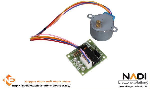
A stepper motor or step motor or stepping motor is a brushless DC electric motor that divides a. 4 Higher-phase count stepper motors; 5 Stepper motor driver circuits. 5.1 L/R driver circuits. A unipolar stepper motor has one winding with center tap per phase. Each section of windings is. In other projects. 5 phase stepping motor. Tags:stepper motordriver. So with it being a 5-phase motor I would need 5 bridges total to drive the motor?
Hi, Welcome to the forum. Please read the first post in any forum entitled how to use this forum. Qualcomm atheros ar9485 driver windows 7 asus iso.
Then look down to item #7 about how to post your code. It will be formatted in a scrolling window that makes it easier to read. Can you please post a copy of your circuit, in CAD or a picture of a hand drawn circuit in jpg, png?
Including you power supplies, please no Fritzy picture. Can you post a picture of your project too please? What driver do you have? Links to data/specs of driver and stepper. I know its a lot but we need this information to give you accurate answers Thanks Tom. Hi, Thanks for the diagram, you will not be able to power those steppers off the 5V of the MEGA. They will need their own 5V power supply.
Your stepper driver has provision for that as well. Go back and start with just ONE stepper and get it working, you can get one of those geared steppers to work off the arduino power and USB. Do not be surprised if you have to swap the 4 driver outputs around to get the stepper to rotate back and forth. PS I have those components as well, I'll assemble the project with one stepper when I can. Mains Power means your utility AC supply, what is the supply you are using, PC or USB adapter.
Selectable Step Angle and Run Current Control The CVD driver has a step resolution switch to allow for matching the input pulse frequency of the controller. Simply use the step angle setting switch to set the input pulses desired. Output pulses are theoretical values as the Smooth Drive feature ensures maximum step performance operation of the stepper motor.
The Smooth Drive microstepping control will still be utilized. Smooth Drive is a function to achieve lower vibration and noise at low speed operation without changing the step angle setting.
This function divides the step angle automatically in response to the pulse signals. There is no need to change the setting of the pulse signals (speed, number of pulses) on the controller side.
Set the smooth drive function with the OFF/SD selection switch. Run Current The motor current for when inputting pulses (operating current) can be changed with the RUN Current switch.
If the load is small and there is an ample allowance for torque, motor temperature rise can be suppressed by setting a lower operating current. The operating current is a value in which the operating current rate is multiplied by the rated current (100%). Minimum current is 25% of rated and selectable in 5% increments. The CVD Driver can also be used with lower amperage stepper motors. Use the Run Current Selection Switch to match the motor current ratings.
Standstill Current When the motor stops, the current cutback function will be actuated to lower the motor current to the standstill current. The driver standstill current rate can be switched between 25% and 50% using the STOP switch.

When setting the switch to the OFF side, the standstill current rate will be set to 25%. Then setting the switch to the ON side, the standstill current rate will be set to 50%. Alarms Monitor the driver performance for early detection of any abnormalities.
All CVD drivers have built in alarms to alert when there is a problem. The alarms are both a blinking LED and an Alarm signal to an upper controller.
Alarms range from Overheat, Overvoltage, Overcurrent to EEPROM error and CPU error.